Drawings: connections
Stage 1 wiring: ESP32 DevKit, PCA9685 16-channel 12-bit servo driver (0x40) and 0.96" SSD1306 OLED (0x3C) on one I2C bus, 16 MG90S servos on their own power bus.
Wiring diagram
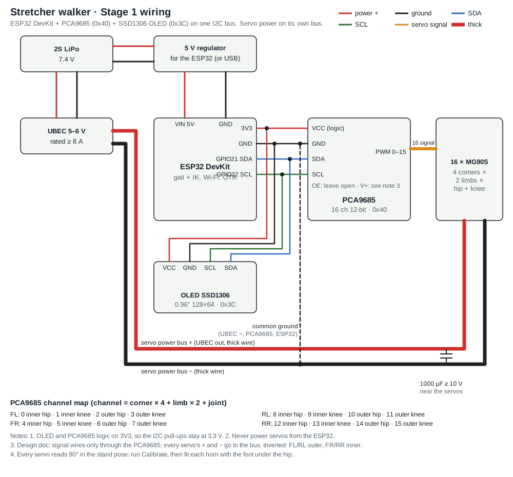
Power
| From | To | Notes |
|---|---|---|
| 2S LiPo (7.4 V) | UBEC input | |
| UBEC out + (5–6 V) | servo power bus + → every servo’s red wire | UBEC rated ≥ 8 A, thick wire |
| UBEC out − | servo power bus − → every servo’s brown wire | thick wire |
| 1000 µF capacitor (≥ 10 V) | across the servo bus | near the servos |
| 2S LiPo | 5 V regulator → ESP32 VIN (5V) | or USB; the ESP32 gets its own 5 V |
| UBEC −, PCA9685 GND, ESP32 GND, OLED GND | joined | common ground; without it the signals don’t work |
Logic and I2C
| ESP32 pin | PCA9685 | OLED SSD1306 |
|---|---|---|
| 3V3 | VCC (logic) | VCC |
| GND | GND | GND |
| GPIO21 (SDA) | SDA | SDA |
| GPIO22 (SCL) | SCL | SCL |
| – | OE: leave open | |
| – | V+: not used for servo current (see notes) |
I2C addresses: PCA9685 0x40, OLED 0x3C. Logic runs at 3.3 V, so the I2C pull-ups stay at 3.3 V.
Servo channels (PCA9685)
Channel = corner × 4 + limb × 2 + joint. Corners FL, FR, RL, RR; inner limb then outer; hip then knee. Plug each servo’s signal (orange) wire into its channel; red and brown go to the servo power bus.
| Ch | Corner | Limb | Joint | Mount |
|---|
Notes
- Never power the servos from the ESP32 or through its regulator.
- Design doc rule: signal wires only through the PCA9685; every servo’s + and − go to the servo bus, not through the board’s V+ terminal.
- Right-side corners (FR, RR) mount mirrored, so their servos start inverted in the software.
- Every servo reads 90° in the stand pose: run Calibrate, then fit each horn with the foot under the hip.